
CLUTCH COMPONENTS
PLANT PROCESS
Out sorucing components
CLUTCH DISC
-
1
CLUTCH FACING -
2
DAMPER SPRING -
3
STOP PIN -
4
RIVET
Out sorucing components
CLUTCH COVER
-
1
RIVET -
2
FULCRUM RING
PLANT PROCESS for CLUTCH DISC
-
1
PRESSING & FORMINGFor all the metal parts -
2
MACHININGFor clutch hub -
3
BROACHINGFor clutch hub -
4
HEAT TREATMENTFor all the metal parts -
5
ASSEMBLING(RIVETING) -
6
TESTING -
7
PACKING
PLANT PROCESS for CLUTCH COVER
-
1
PRESSING & FORMINGFor all the metal parts -
2
MACHININGFor pressure plate -
3
HEAT TREATMENTFor diaphragm spring -
4
ASSEMBLING(RIVETING) -
5
TESTING -
6
PACKING
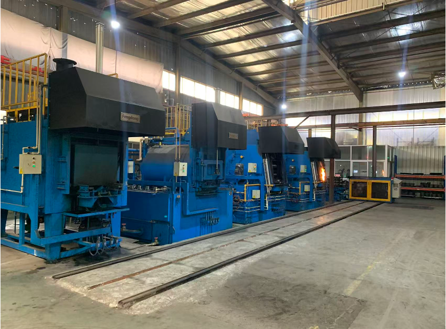
HEAT TREATMENT
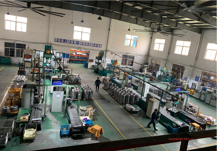
ASSEMBLING PROCESS
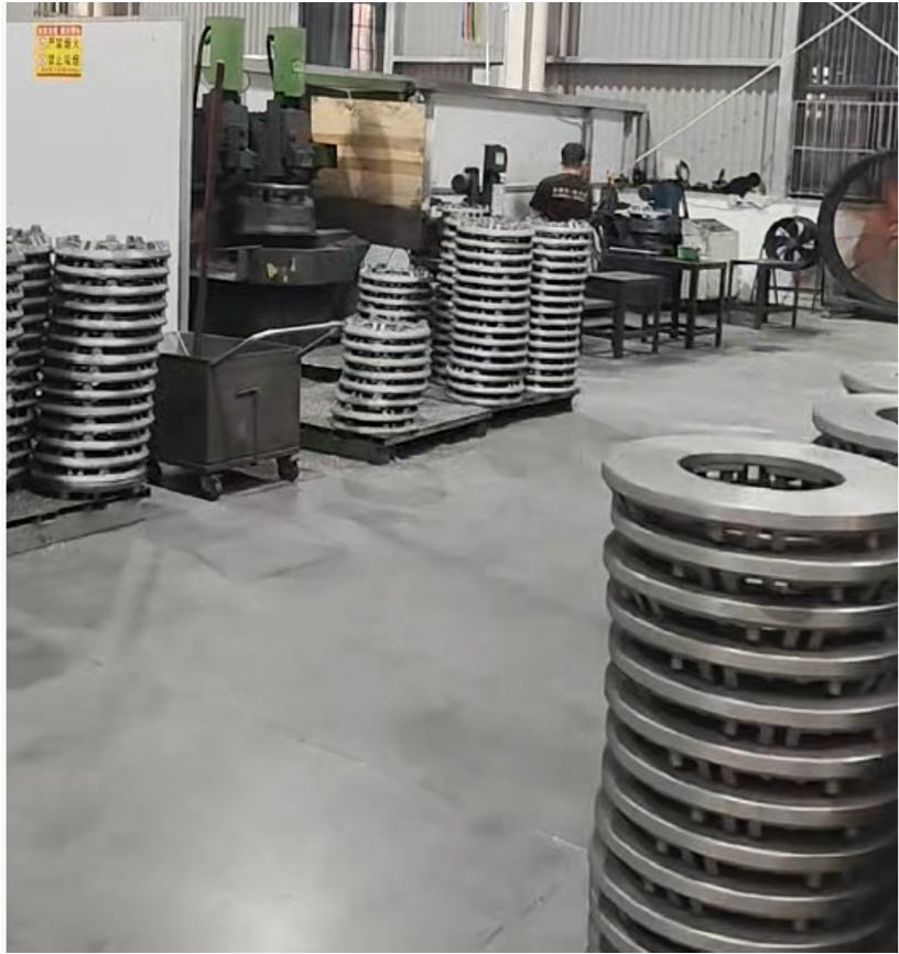
MACHINING
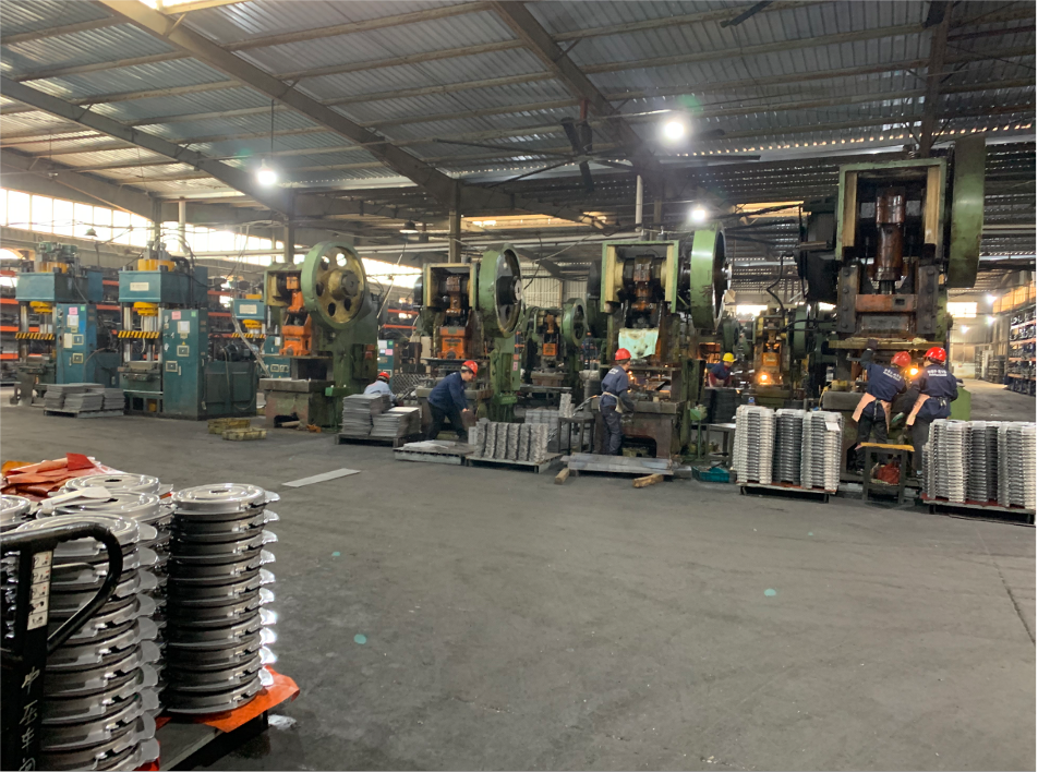
PRESSING
CLUTCH Installation Instructions
In the process of automobile maintenance and assembly, the clutch, as a key component of the transmission system, is crucial for vehicle performance and driving safety. This article will provide a detailed explanation of the correct steps for installing the clutch and offer an in-depth analysis from multiple perspectives to ensure the rigor and accuracy of the installation process.
1. Preparations
1.1 Tools and Accessories Confirmation
Make sure to have a complete set of clutch components (including the pressure plate, clutch disc, release bearing, pilot bearing, etc.) as well as specialized tools such as a torque wrench, socket wrench, puller, etc. Check that the new clutch components are intact and that the model and specifications match the original vehicle.
1.2 Remove the old clutch
Remove the flywheel housing, clutch assembly, and related mounting bolts and brackets step by step in reverse order.
2. Clutch Assembly Installation Steps
2.1 Cleaning and Inspection
Flywheel Cleaning and Inspection: Use a professional cleaner to thoroughly clean the surface of the flywheel, ensuring it is free of oil, rust, or excessive wear. Check the flatness of the flywheel; if there is significant deformation, it needs to be repaired or replaced.
Installing a New Clutch Disc: Place the new clutch disc between the flywheel and pressure plate in the specified direction, making sure not to apply any grease to the friction surfaces.
2.2 Installing the Pressure Plate and Release Bearing
Install the pressure plate by placing the new pressure plate assembly onto the clutch disc, ensuring all alignment pins and bolt holes are aligned. Use a torque wrench to tighten the bolts to the manufacturer’s recommended specifications.
Install the release bearing by correctly mounting it onto the transmission input shaft and adjusting the preload clearance to ensure the clutch can engage and disengage properly.
2.3 Guide Bearing and Push Rod Assembly
Install the guide bearing into the clutch pedal mechanism, ensuring it rotates freely without any sticking.
Adjust the push rod according to the vehicle manual, setting the clutch pedal push rod length to guarantee that when the clutch is fully released, the release bearing can effectively push the pressure plate to disengage.
3. Final Adjustment and Inspection
Clutch Travel Adjustment: Adjust the clutch pedal free play to the specified range to ensure smooth clutch engagement, without slipping or incomplete disengagement.
Test Drive Inspection: After installation, perform a test drive to assess the clutch’s performance through actual driving experience. If any abnormalities are noticed, stop immediately to check and readjust.
In short, the correct installation of the clutch not only requires strict adherence to the operating procedures but also demands that technicians have extensive professional knowledge and practical experience. Only in this way can it be ensured that the clutch performs at its best during vehicle operation, prolongs its service life, and ensures driving safety.
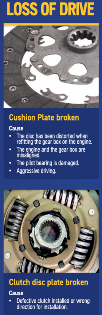
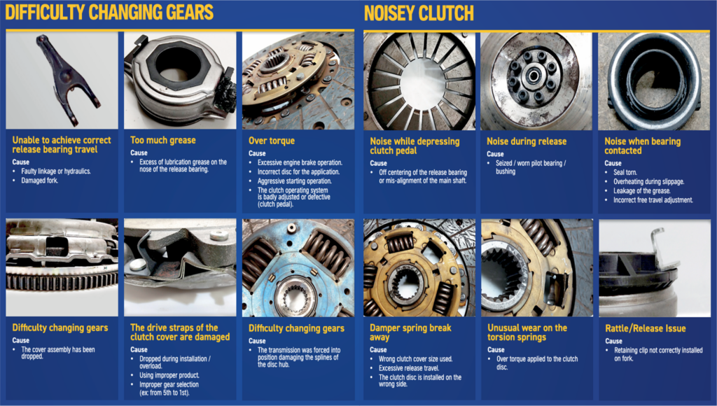
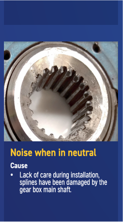
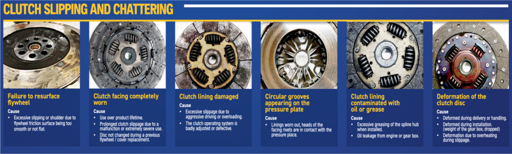
Troubleshooting

Technical recommendation
What to keep in mind when assembling the clutch
• The complexity of the clutch assembly is often underestimated.
• Avoid unnecessary and costly whole unit repairs by seeking expert advice prior to change.
• Damage to the clutch can have serious consequences for the transmission.
• Pay strict attention to installation position, lateral run-out, centering and cleanliness.
Clutch assembly is demanding and time-consuming as it requires the transmission to be separated from the engine. To avoid often unnecessary and costly replacement of the entire unit, prior assessment is indispensable.
The clutch is the link between the engine and transmission – and one of the most durable wear parts. There are many factors which can result in a clutch defect. For example, the clutch is frequently placed under heavy load due to frequent driving with a trailer or a faulty engine management system. Before replacing the entire unit at great cost, the specialists advise you to always check the surrounding components in the event of clutch malfunctions – including the clutch actuation and the seals of the engine, flywheel and transmission.
Examining the clutch disk before assembly
The clutch disk, also known as the drive plate, is subjected to the greatest load, because the clutch’s mode of operation results in mechanical abrasion. For this reason, the clutch disk must have high wear and high temperature resistance. However, it makes sense to double check the condition of the ackaging and the new part before installation, as it may have been damaged during transport or because of improper handling. To be completely certain of the condition of the part, make sure that the lateral run-out of the disk does not exceed the limit value of 0.5 millimeters. If it does, this can be corrected using a straightening fork.
Pay attention to the installation position and precisely center the clutch disk.
Make sure when installing the clutch disk it is in the right position. Incorrect installation would result in damage to the disk itself, its hub spline, release lever or even to the transmission. Fitting instructions can usually be found on the component side. If no indications can be found,compare the new part with the old one before installation.The new clutch disk must be precisely centered to prevent damage to the hub spline. There is a tolerance range of only a few hundredths of a millimeter between the transmission input shaft and the hub spline. Even small inaccuracies during insertion of the transmission input shaft can prevent the mobility later required for disengaging the clutch. The hub spline must slide onto the transmission shaft without resistance.
Install the pressure plate by placing the new pressure plate assembly onto the clutch disc, ensuring all alignment pins and bolt holes are aligned. Use a torque wrench to tighten the bolts to the manufacturer’s recommended specifications.
Install the release bearing by correctly mounting it onto the transmission input shaft and adjusting the preload clearance to ensure the clutch can engage and disengage properly.
The specialist recommends greasing the hub spline with high performance grease. Its viscous consistency and temperature resistance means it adheres to the spline during operation without spreading. In order to prevent clutch shudder when the clutch is later disengaged,excess grease must always be removed, and care must be taken to keep the clutch linings absolutely clean.
We are TRIFORCE, the best Clutch kits & Cylinder Factory
SUBSCRIBE
Design by ADVICOM © All rights reserved Copyrights 2026